Electrical Engineering has been shaping the world we live in, enabling most of the technology that we use every day. What looked like pure science fiction just some time ago, is now electrical engineering enabled science faction. This includes mobile phones, wireless data access, augmented and networked gaming, computers, computerized control for mechanical systems, internet-of-things devices, medical systems, robotics, self-driving cars and much more. All these devices and systems have two things in common: The functionality enabled by the electrical engineering core is very visible whereas the actual electrical engineering core itself is not visible.
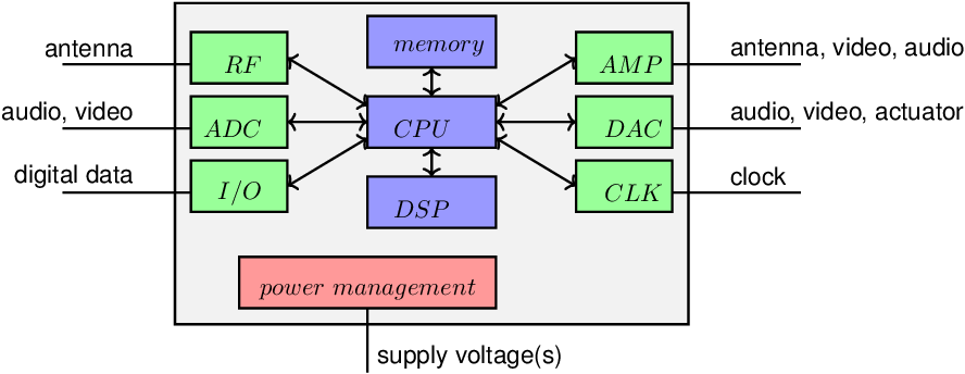
The invisible workhorses in electrical engineering are the chips, the integrated circuits. They contain signal processors, provide digital computational power and include circuits to receive data from and send data to the physical real world. As the physical world is analog (on the scale we perceive it), the circuits that interact with the physical world are analog by nature. Examples of these include audio amplifiers, transmit and receive circuits, analog-to-digital converters (ADCs), digital-to-analog converters (DACs), sensor interfaces, actuator drivers, ...
Many of these chips are small, spanning a few square millimeters. On that small area a complete system can be built, nowadays containing easily multiple kilometers of metal interconnect lines between millions, or even billions of transistors. Most of these transistors are truly invisible: smaller than a tenth of the wavelength of visible light...
In this book the main focus is on the basics of electronics.
By no means this book covers everything in the system in Figure 1.1: only the basics of analog amplifiers, feedback, harmonic oscillation and some basics of radio frequency systems are treated. Especially no digital circuitry, digital signal processing and no ADCs nor DACs are dealt with. Sorry that there is no time to discuss these as well. Leveraging the basics that are presented in this book, the operation of digital and mixed signal circuits can however be understood.
Derivations and calculations using non-linear components are in general hard. Still, we need non-linear components in virtually any useful electronic circuit. Obviously, non-linear operations require non-linear components. In general electronic systems contain many explicit non-linear operations:
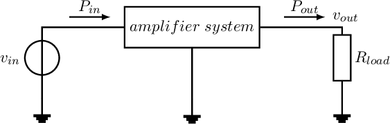
Apart from these, circuits or systems that can give a power gain larger that unity are fundamentally non-linear, to simultaneously satisfy the properties of linearity and to obey the law of conservation of energy. In this context, power gain is defined as the ratio between the power of the input signal and the power of the output signal of the system. Such a system is depicted below:
Assuming (just as example) a sinusoidal and an input resistance of the amplifier block equal to , the input (signal) power into the amplifier is
Assuming a linear amplifier block, the output signal is sinusoidal at the same frequency, with possibly a different amplitude and phase. The power dissipated in the load resistor is
From the law of conservation of energy (per unit time), it follows that : the power dissipated in the load cannot be larger than the total input power provided to this amplifier system, which equals . can be lower than in which case the difference in power is converted into heat in the amplifier block13 .
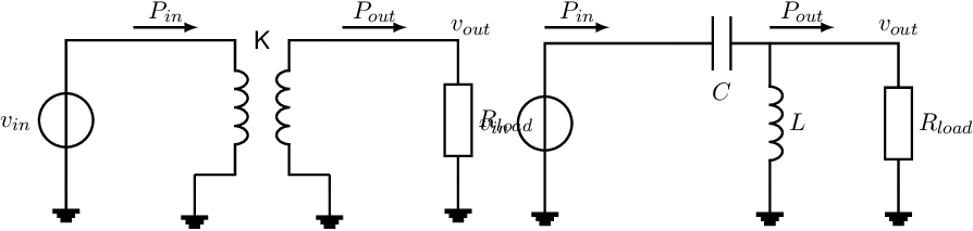
Note that either the voltage gain or the current gain can be higher than unity, but their product cannot be larger than unity. Two examples of linear circuits that can achieve either or , with , are shown below.
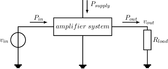
It can be concluded that to get a system where , there must be an extra power (or energy) source that lets the amplifier create an output power that exceeds the input power level. In this case which complies to the law of conservation of energy (per unit time), where the difference in total (electrical) input power and (electrical) output power is dissipated into heat.
Now 2 situations can occur:
The next conclusion is hence that
Similarly,
The workhorse for nowadays electronics is the transistor: a component that can be used to execute non-linear operations and that can be used to construct circuits that have a power gain larger than unity. Transistors are hence fundamentally non-linear. Transistors come in a number of variants; in this book we use the bipolar junction transistor and the MOS-transistor. The basic physics behind these is explained in chapter 2. Using transistors in amplifiers, to construct opamps, to make oscillators and radio-frequency circuits is done in the rest of this book.
Throughout this book, for readability reasons,
Background information, or extra information is usually printed using a somewhat smaller font on a gray background.
An exception to this notation rule is all content in chapter 0, dealing with preparatory knowledge. This could have been typeset as background information but it is typeset as regular text.