Exercise 5.6 A common-gate amplifier and a something else
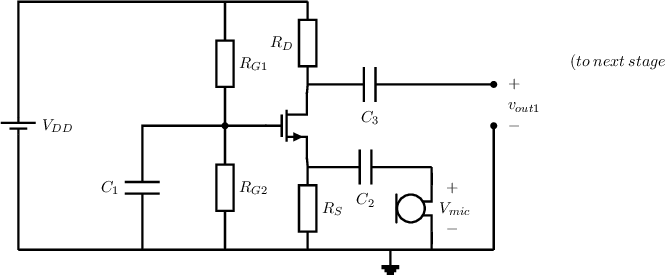
Below, the circuit schematic of the input stage of a dynamic microphone pre-amplifier is shown. Note that it resembled
the amplifier in the previous exercise, but now uses MOS transistors. The microphone voltage is indicated by
. The power supply
voltage . The transistor
has a threshold voltage ,
and .
For the signal frequencies of interest all capacitors are low impedant.

-
a)
- Draw the small signal equivalent circuit of the MOS pre-amplifier input stage, loaded by a next
stage that has input resistance .
-
b)
- Derive an expression for the voltage gain
of the circuit, including the input resistance
of the next stage.
-
c)
- Derive an expression for the input resistance of the amplifier, as seen by the microphone.
-
d)
- Calculate the required drain current for an input resistance of .
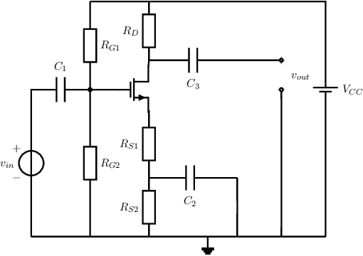
The next figure shows the schematic of the second amplifier stage that is used to further amplify
the voltage from the input stage. Again, ,
,
and for the signal frequencies of interest all capacitors may be considered as low ohmic.

-
e)
-
Draw a small signal equivalent circuit for the second amplifier stage.
-
f)
- Derive an expression for the voltage gain
of the second amplifier stage.
-
g)
- Derive an equation for
to get a specific ,
assuming square law operation and assuming that the other component vales are known.
-
h)
- The second stage is dimensioned for a drain current of
with ,
,
.
Calculate (numerically) the required value of .
-
i)
- Calculate the numerical value of the voltage gain of the second amplifier stage.


