An answer:
Assuming stable behavior, for an ideal opamp which yields directly
An answer:
At the unity-gain frequency, the modulus of the gain is 1 by definition, leading to
Another approach is by drawing a Bode plot. Asymptotically, the (angular) corner frequency lies at at a gain of , and rolls-off first order for higher frequencies. It crosses the zero dB axis if the (modulus of the) gain is reduced by a factor . Being a first order system that must be at a frequency factor of higher than the corner frequency.
An answer:
The loop consists of (in arbitrary order):
- the transistor, which translates into a transconductance for small signals
- the resistive divider with
- the opamp (via the non-inverting input
The loop gain is then
An answer:
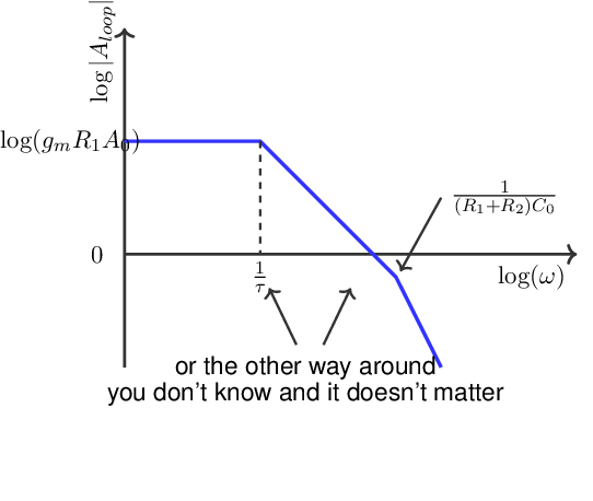
It was stated that the unloaded regulator is stable, with a sufficient phase margin. Furthermore the loop gain at DC is probably much larger than unity because . This implies that the (magnitude part of the) Bode plot of is as shown below:
- there are two poles, where the second one is located at frequencies where (for sufficient phase margin)

A higher increases the of the transistor. That shifts the curve in the Bode plot upwards, which decreases the phase margin.