An answer:
From the Bode plot, we can see that the op-amp transfer function has a DC gain of ,
and three poles. The first pole is at ,
the second one at ,
and the third one at .
After the first pole, the slope is 20 dB/decade. After the second pole it is 40 dB/decade and after
the third pole it is 60 dB/decade.
This shows that the op-amp transfer function can be written as the cascade (for gain: multiplication) of three first-order transfer functions:
An answer:
Configuration (a) has positive feedback and configuration (b) is inverting, which leaves
configuration (c) and (d) to choose from. Now, let’s observe the op-amp transfer function again:

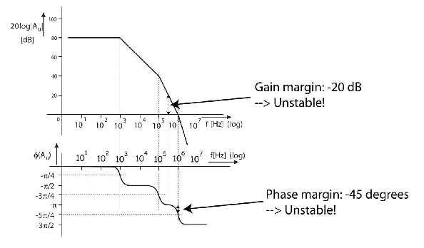
Suppose we would apply unity feedback (). In that case , so the loop transfer is simply the transfer of the op-amp itself. For unity gain feedback, we can read the gain margin by checking the gain at a phase of -180 degrees. This turns out to be -20 dB, the resulting amplifier using would be unstable. We can also check the phase margin by checking the phase at a gain of 1 ( 0 dB). This turns out to be , so the phase margin (distance to ) is . This also indicates instability.
In other words, the op-amp is not “unity gain stable”: If we apply a feedback network with a transfer of , the closed-loop circuit is unstable. For unity gain stability, at least phase margin is required.
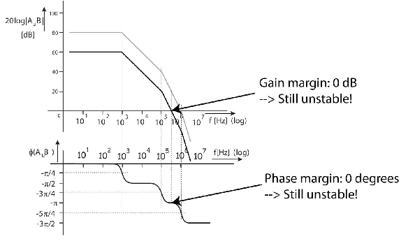
For the circuit in (d), the feedback network has a gain of dB. So the open-loop loop transfer for the circuit is (d) is simply the opamp voltage gain, downshifted by 20 dB. This is shown below:

We can see that the circuit has (close to) zero gain and phase margin, so it is still unstable or at best very close to instability.
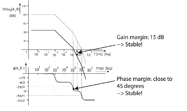
For the circuit in (c), the feedback network has a gain of dB.

We can read a gain margin of 15 dB and a phase margin close to . So, the closed-loop transfer of this circuit is stable. Also, for the desired frequency range of kHz, the circuit has (close to) 20 dB closed-loop gain.
An answer:
This has been done graphically in (b).
The phase margin can be calculated by evaluating the (angular) frequency for which and checking . That is however computationally a lot of work: after maximum simplification of the loop gain, we are still left with a high order function of ...
Calculating the gain margin is a lot easier. The above approximation for can be used to get the (angular) frequency at which . Then that can be used to get the gain margin . Straight forward algebra (or plain symmetry) shows that
which can be used to calculate and thereby to calculate the gain margin.
An answer:
From 0 to 10 kHz, we only have to consider the first pole of the op-amp.
The output resistance of this type of non-inverting amplifier circuit with a voltage can be derived to be:
Plugging in the frequency-dependent gain of the opamp:
Of course, this can be written in more convenient forms. And in more inconvenient forms.