Exercise 11.1 Transmit power
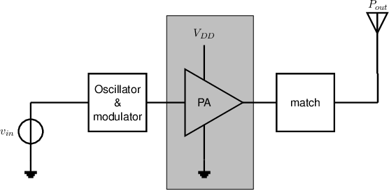
The figure below shows a (quite generic) setup of an RF transmitter, consisting of a power amplifier
(PA) that is driven by a modulated oscillator and that drives an antenna. Between the PA and
the antenna there may be an extra matching network. The complex antenna impedance is
. The maximum output
current of the PA is while the
maximum voltage swing is .

-
a)
- Explain (briefly & clear) why an antenna that actually transmits has a finite non-zero real part
in the antenna impedance .
-
b)
- The impedance of a(n about) quarter-wave monopole antenna is purely real. Connecting this
antenna directly to the output node of a PA – having both the intended RF signal and a non-zero
DC-(bias) voltage – without coupling capacitor does not result in any DC power into the antenna.
Explain this.
-
c)
- Derive an expression for the maximum transmit power of the system described above the figure.
-
d)
- Derive 2 expressions for the ratio between the transmit power (at the same PA output voltage
swing) when on one hand a short antenna with
and compared to using:
1) a short antenna with “match” for which
(1st expression)
2) a
antenna with
(2nd expression)

