Exercise 9.13 An harmonic oscillator?
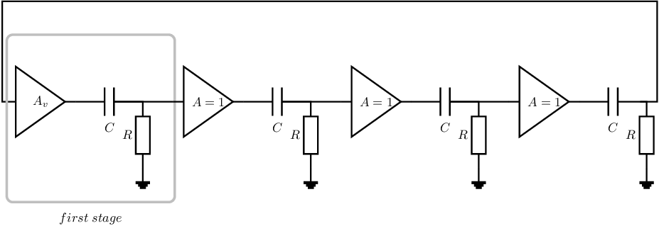
Given is the circuit below; this circuit is intended to be an harmonic oscillator.
- The voltage gain of the voltage buffer at the left hand side of the schematic is a real valued factor
in questions (a)-(d); this value can be positive or negative. The voltage gain of the other voltage
buffers is 1; for all voltage buffers
and .
- The value of all resistors is the same (R), the capacitors have identical values (C), and all
inductors have identical values (L) - this is to simplify your derivations.

-
(a)
- Which condition(s) must be satisfied to get harmonic oscillation?
-
(b)
- Derive the voltage transfer for each of the 4 stages in the figure. Combined these form the loop
gain.
-
(c)
- Draw a Bode plot (magnitude and phase) of the loop gain; for this question you may assume
,
and
when making this plot.
-
(d)
- Determine whether the given circuit can function as harmonic oscillator for a specific positive
(real) value of .
If your answer shows that harmonic oscillation can be possible, derive an expression for the
(radian) oscillation frequency and for the required .
-
(e)
- Determine whether the given circuit can function as harmonic oscillator for a specific negative
(real) value of .
If your answer shows that harmonic oscillation can be possible, derive an expression for the
(radian) oscillation frequency and for the required .

