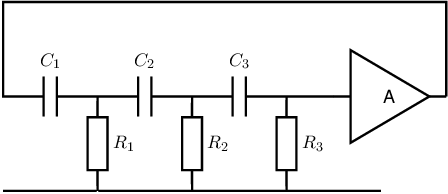
Exercise 9.4 A 3-stage RC-phase shift oscillator
The circuit schematic below shows the circuit of an RC phase shift oscillator. In this
circuit you can assume that the RC sections hardly influence each other because
and
. You
may assume that there is no influence whatsoever as simplification.

-
a)
- Derive an expression for the voltage transfer of the feedback network
consisting of the three RC stages (that is from the output of the amplifier to the input of the
amplifier).
-
b)
- Draw a Bode plot (magnitude and phase) of the feedback network.
-
c)
- Derive an expression for the oscillation frequency
or the radian oscillation frequency .
-
d)
- Derive an expression for the amplifier gain A needed for harmonic oscillation.
-
e)
- Draw a polar plot of A
and indicate relevant angular frequencies ,
,
and .

