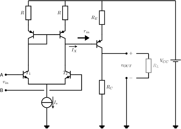
Exercise 8.8 An opamp circuit schematic
The figure below shows the circuit of a simple opamp, consisting of a differential
pair, current mirror and an output stage. For all transistors it is given that if
and
,
is not very
large, and .

-
a)
- Draw a small-signal equivalent circuit for the differential pair and derive an expression for the
small-signal transfer of the differential pair
where .
Define the sign of
explicitly.
-
b)
- Draw a small-signal equivalent circuit for the current mirror and derive an expression for the
small-signal current transfer of the current mirror.
-
c)
- Derive an expression for the small-signal transfer from
to .
Remember that
is not very large and hence explicitly must be taken into account.
-
d)
- Derive an expression for the small-signal input resistance
of the output stage.
-
e)
- Derive an expression for the small-signal voltage gain
of the entire opamp.
It is given that
and the bias current through the output transistor is also .
Furthermore, ,
and .
-
f)
- Calculate the numerical value of the gain of the opamp.
-
g)
- Which one of the inputs (A or B) is the non-inverting input?
-
h)
- Derive an expression for the input resistance of this opamp and calculate the numerical value.

