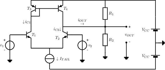
Exercise 8.5 A simple opamp schematic
In the circuit below, the NPN transistors
and are identical; for
these NPNs . Also the
PNP transistors and
are identical; for these PNPs,
. For all four transistors the
small-signal output resistance
can be neglected.
For the circuit, ,
, and
.

-
a)
- Give an estimate for the current
as defined in the circuit, for .
-
b)
- Let’s assume that we apply
and .
Estimate or calculate the resulting .
-
c)
- Let’s again assume that we apply
and .
Estimate or calculate the resulting .
-
d)
- Derive or approximate the value of
for .
-
e)
- Derive or approximate the value of
for .
-
f)
- To increase the circuit’s input voltage range, emitter resistors
are inserted in series with the emitters of
and .
Estimate the increase in input voltage range for .
For this, you may assume that the range is limited by the values for which
of
is flowing through either
or .

