Exercise 9.9 An harmonic oscillator?
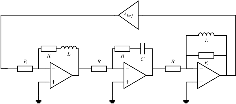
Given is the circuit below; this circuit is intended to be an harmonic oscillator.
- The opamps are ideal, with a real valued voltage gain
and with no frequency dependency.
- The voltage gain of the voltage buffer at the top of the schematic is a real valued factor
;
this value can be positive or negative.
- The value of all resistors is the same (R), the capacitors have identical values (C), and all
inductors have identical values (L) - this is to simplify your derivations.

-
(a)
- Which condition(s) must be satisfied to get harmonic oscillation?
-
(b)
- Derive the voltage transfer for each of the 3 stages at the bottom of the figure. Each stage starts
at the output node of the previous opamp/amplifier and ends at the output node of the opamp
in the stage.
Combined with the
this forms the loop gain.
-
(c)
- Determine whether the given circuit can function as harmonic oscillator for a specific (real) value
of .
If your answer shows that harmonic oscillation can be possible, go to question (d). Otherwise
go to question (e).
-
(d)
- IF harmonic oscillation possible at question (c): derive an equation for the oscillation frequency
AND (after that) derive an equation for the required value of .
Both these equations should be functions of the various component values in the schematic —
they may be ugly equations. After finishing (d) skip (e).
-
(e)
- IF no harmonic oscillation possible at question (c): swap a resistor and the reactive component
in one of the stages in such a way that harmonic oscillation can be achieved, and then redo
questions (c) and (d). IF there is no way to get the circuit to oscillate harmonically: prove that!

