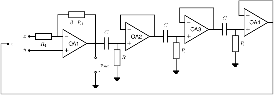
Exercise 9.1 AN RC-phase shift oscillator
The op-amps in the phase-shift oscillator below are all ideal: symmetrical,
,
and
. The
circuit is designed to create a harmonic signal.

-
a)
- Derive an expression for the signal transfer of each of the 3 (identical) stages at the right hand
side of the oscillator.
-
b)
- Derive an expression for the total (combined) signal transfer of the 3 (identical) stages.
-
c)
- Draw a Bode plot (magnitude and phase) of the transfer function of one of the 3 stages AND of
the combined 3 stages. For these Bode plots you may use e.g.
and .
-
d)
- Node
will be connected to either
or .
The node that is NOT connected to
will be connected to ground. Determine which of the nodes
and
of OA1 has to be the inverting one to obtain oscillation.
-
e)
- Derive an equation for the (radian) frequencies/frequency for which this transfer is purely real
-
f)
- Determine the value of
such that the oscillation condition is satisfied.

