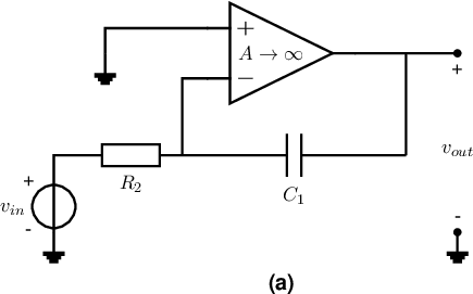
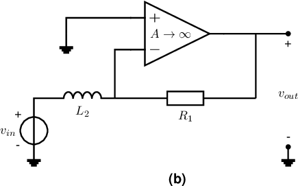
Exercise 6.1 Opamp configurations with reactive components
The figure below shows 2 circuits consisting of an opamp with a feedback network. In this exercise you may
assume that the opamps are ideal, with infinite voltage gain.


-
a)
- Derive a relation for the signal transfer
of the circuit with the capacitor, in figure (a).
-
b)
- Derive a relation
of circuit (a) - the one with the capacitor. Note that this is a time domain transfer.
-
c)
- Derive a relation for the signal transfer
of the circuit with the inductor, in figure (b).
-
d)
- Derive a relation
of circuit (b): the one with the inductor. Note that this is a time domain transfer.


